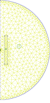
A test for FEMM is the calculation of the magnetic field, which is generated by the field coil. The experimental data are given in table 1.
A mesh of 705 nodes and 1186 elements has been used to calculate the field on the axis in the centre of the coil. A static current was assumed.

Figure  : Finite element mesh of the single turn coil

Table  : Magnetic field of the single turn coil
The results of the calculations are in agreement with the experimental values. In the numerical simulation, the current to field ratio is constant (which we expect for a constant current density over the cross section of the coil) and in good agreement with the experimentally measured data. There are only two data sets (both of them are data of the second halfwave with the 8 mF capacitor), for which the current/field ratio is too high. This can be explained by the fact, that the experimental setup includes a free RLC oscillator circuit, which generates a damped pulse. The damping has to be considered, when calculating the field. However, our harmonic approximation cannot take this into account.
If a harmonic current with a frequency of 112 Hz is applied, the induction on the axis drops to an amplitude of 0.4238 T for a maximum current of 11.4 kA. The reason is, that the harmonic analysis solves the quasistatic problem and includes self inductance and eddy currents within the coil. However, the current pulse in the experiment lasts for only one period. Thus, the system cannot reach equilibrium. In order to avoid this effect, the conductivity of the coil has been set to zero in all following calculations. As FEMM still allows us to define a current, we get rid of the above mentioned effects.
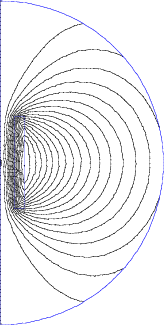
Figure  : Flux lines of a single turn coil with static current
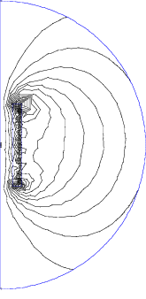
Figure  : Flux lines of a single turn coil with harmonic current
With the detailed model of the coil, which consists of 4 layers of 24 turns each, the results given in table 5 were obtained. Once again we find differences between experiment and simulation for one data set, which has already been discussed in the previous section.

Table  : Magnetic field of the detailed coil model
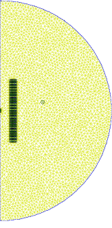
Figure  : Finite element mesh of the detailed coil model
The finite element mesh consists of 6108 nodes and 11946 elements.
For a harmonic current of 11.4 kA at 112 Hz with a conductivity of 55.8659 MS/m of the coil, the induction on the symmetry axis in the centre of the coil drops to an amplitude of 0.4123 T. If we set the conductivity of coil to zero we find an amplitude of 5.64 T for the induction.
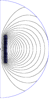
Figure  : Flux lines of the detailed coil model
![]()
![]()
![]()
![]()
Next: Eddy currents
Up: Calculation of eddy currents
Previous: Finite element models
Contents