


Next: Comments on release 2.1a of femm
Up: Calculation of eddy currents
Previous: Induced magnetic moment
Contents
Eddy currents in a solid sphere
Analytical solution
Beware:
There is a problem with this analytical solution (email from David Meeker):
From: Dcm3c@aol.com
Date: Tue, 5 Oct 1999 01:02:53 EDT
To: femm@egroups.com
Subject: [femm] Re: Problems with axisymmetric problems
Thanks for the note--your writeup is pretty interesting. However, I think
that femm is actually doing the correct thing in the case of the small
spheres; something seems to be wrong with the analytical solution presented
for this case.
To see the problem, the easiest case to consider is the one corresponding to
Figure 31 (below).
In this case, a copper sphere with a radius of 3.65 mm and a conductivity of
sigma=56.82 MS/m is exposed to a source field of a Bsrc=1 Tesla amplitude
varying at 109.89 Hz (omega=690.46 rad/sec). This apparently corresponds to
the miniturnsphere.fem example problem.
This is a good case to consider because the radius and frequency are small
enough that the reaction field from the eddy currents can be neglected (The
skin depth at this frequency and conductivity is 6.4 mm. Since the skin
depth is substantially greater than the radius of the sphere, neglecting the
reaction currents for the purpose of estimating the induced current density
is reasonable). When you can ignore the reaction currents, you can
substitute directly into Faraday's law to get an expression for the eddy
current density:
J=-j*omega*sigma*r*Bsrc/2
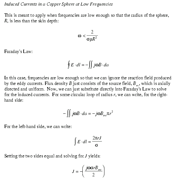
This formula predicts an eddy current density of 71.6 MA/m^2 at the farthest
radius of the sphere. Looking at the finite element solution, the amplitude
of the induced current density at the point (r=3.649,z=0) is 71.63 MA/m^2,
showing a good agreement.
Now, evaluating the sphere.nb Mathematica notebook under the above conditions
yields a current 106.8 MA/m^2, which is substantially larger than one might
expect.
So, what is the difference? I loaded sphere.nb into Mathematica and took the
power series about omega=0 using the Series[] function and subsitituted in
mu0 for mu, since we are considering the copper sphere. The result is:
J=-j*(3/4)*omega*sigma*r*Brc
Now, this doesn't match the low-frequency limiting case that that one can
obtain from Faraday's law. There is an extra factor of 3/2 in there for this
limiting case.
For a solid sphere in a uniform sinusoidal magnetic field with an amplitude of 1 T the magnetic vector potential A can be calculated analytically [7]. In the sphere it is given by
 (
(  )
)
 (
(  )
)
and in empty space it is
 (
(  )
)
 (
(  )
)
where
 (
(  )
)
 (
(  )
)
 (
(  )
)
 are the nth order Bessel functions of first kind,
  is the radius of the solid sphere, and k is given by
 (
(  )
)
Numerical solution
A solid iron sphere with radius rs = 5 cm,mur = 20,sigma = 10 MS/m in a sinusoidally varying magnetic field with an amplitude of 1 T and a frequency of 50 Hz was simulated. The external field was generated by the well known field coil and its current suitably rescaled. Therefore, the magnetic field is not perfectly homogeneous. The finite element mesh consisted of 9324 nodes and 18319 elements.
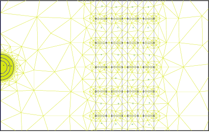
Figure  : FE mesh (small cut out) of the iron sphere and detailed coil model
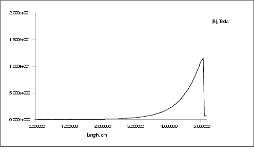
Figure  : Magnetic induction in the iron sphere
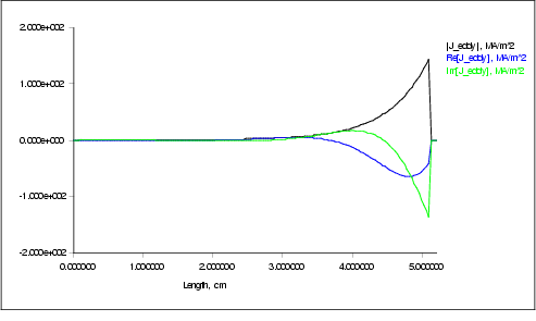
Figure  : Eddy current density in the iron sphere
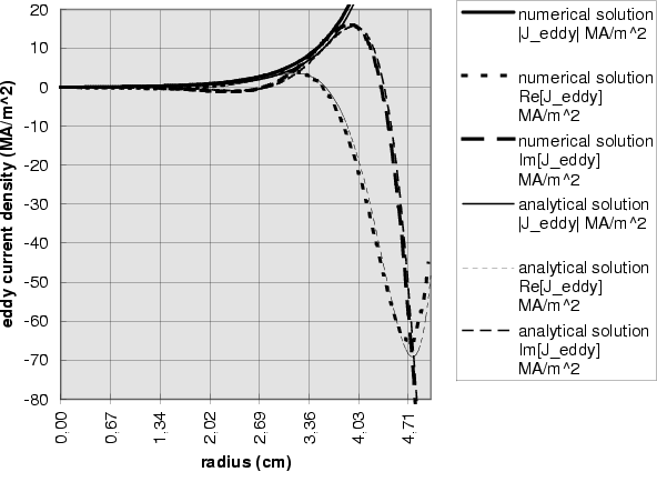
Figure  : Eddy current density in the iron sphere
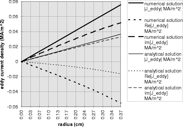
Figure  : Eddy current density in the iron sphere
Sample Cu3
The results for the spherical Copper sample Cu3 in a sinusoidally varying field of 1 T shows a rather large deviation from the analytic results. It has been verified, that the asymptotic boundary conditions do not account for that. Even if the radius of the spherical boundary, where asymptotic boundary conditions apply, is doubled, the results remain almost identical (they cannot be distinguished in the plots below). Also the simple model of the field coil (the single turn coil) leaves the result unchanged. Even if the diameter of the field coil and its height are doubled to improve the homogeneity of the field, no difference in the result can be found.
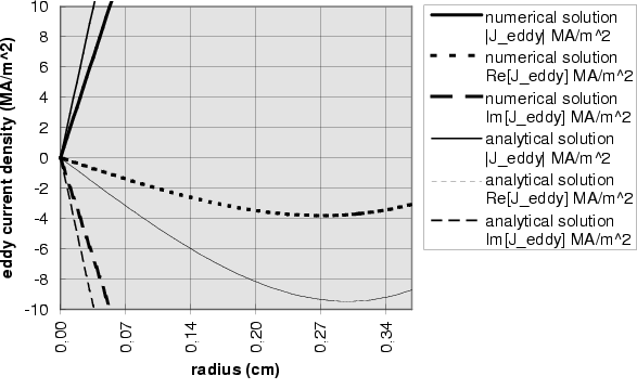
Figure  : Eddy current density in sample Cu2 @ 1 T
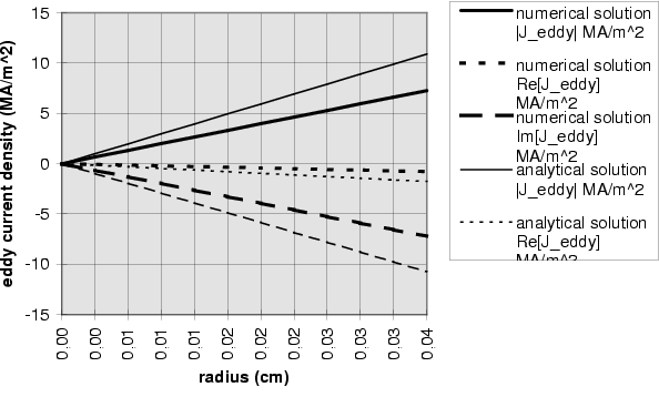
Figure  : Eddy current density in sample Cu2 @ 1 T
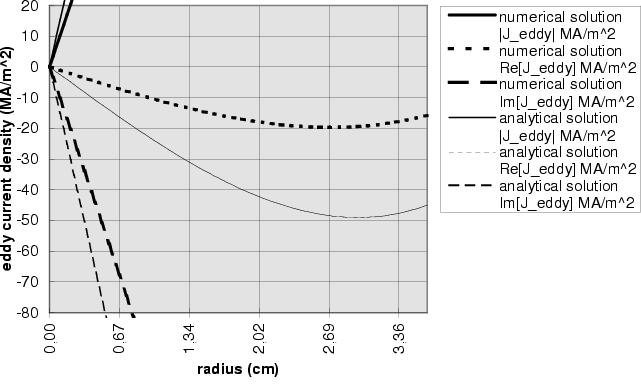
Figure  : Eddy current density in sample Cu2 @ 5.17 T
Frequency dependence
The frequency dependence of the magnetization is shown in the following table (data analyzed and collected by Prof. Grössinger). The magnetization has been plotted as a function of  and the results analyzed by linear regression. The offset gives the value of M for
  , where the magnetization should vanish. However, these values are acceptable, if we take into account, that the magnetization is typically of the order of 100 kA/m.

Table  : Comparison of experimental and numerical results


Next: Comments on release 2.1a of FEMM
Up: Calculation of eddy currents
Previous: Induced magnetic moment
Contents
© 1999
Werner Scholz
werner.scholz (at) tuwien.ac.at

 (
(  )
)
 (
(  )
)
 (
(  )
)
 (
(  )
)
 (
(  )
)
 (
(  )
)
 (
(  )
)
 are the nth order Bessel functions of first kind,
  is the radius of the solid sphere, and k is given by
 (
(  )
)

 : FE mesh (small cut out) of the iron sphere and detailed coil model

 : Magnetic induction in the iron sphere

 : Eddy current density in the iron sphere

 : Eddy current density in the iron sphere

 : Eddy current density in the iron sphere

 : Eddy current density in sample Cu2 @ 1 T

 : Eddy current density in sample Cu2 @ 1 T

 : Eddy current density in sample Cu2 @ 5.17 T
 and the results analyzed by linear regression. The offset gives the value of M for
  , where the magnetization should vanish. However, these values are acceptable, if we take into account, that the magnetization is typically of the order of 100 kA/m.

 : Comparison of experimental and numerical results